


EDGECAM Latest Release – 2013 R2
The most far-reaching enhancement in 2013 R2 is Workflow, enabling CAD/CAM engineers to apply toolpaths within seconds. Other powerful items of new and enhanced functionality include modern redesign of dialogs, four-turret support, free loading of CAD files into Part Modeler, quicker simulation, and improvements to the Wire EDM Feature Finder.
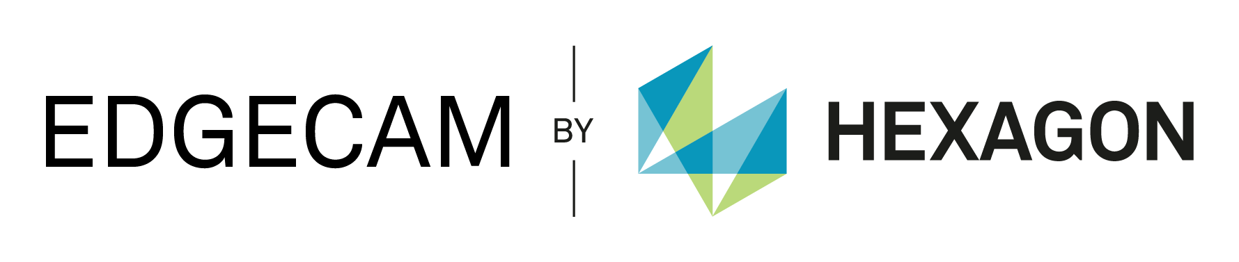
Workflow
Workflow understands the component topology and therefore understands the required manufacturing environment.
The new tools aid in loading and positioning the component, choosing the manufacturing method and suitable machine tools, adding user defined stock or stock from a database, importing fixtures, selecting a machine and toolkit, and managing strategies to automate manufacture. At each stage Workflow takes decisions or makes suggestions as to how the goal is best achieved. However, the user can easily over-ride the decisions if required, making the whole process flexible.
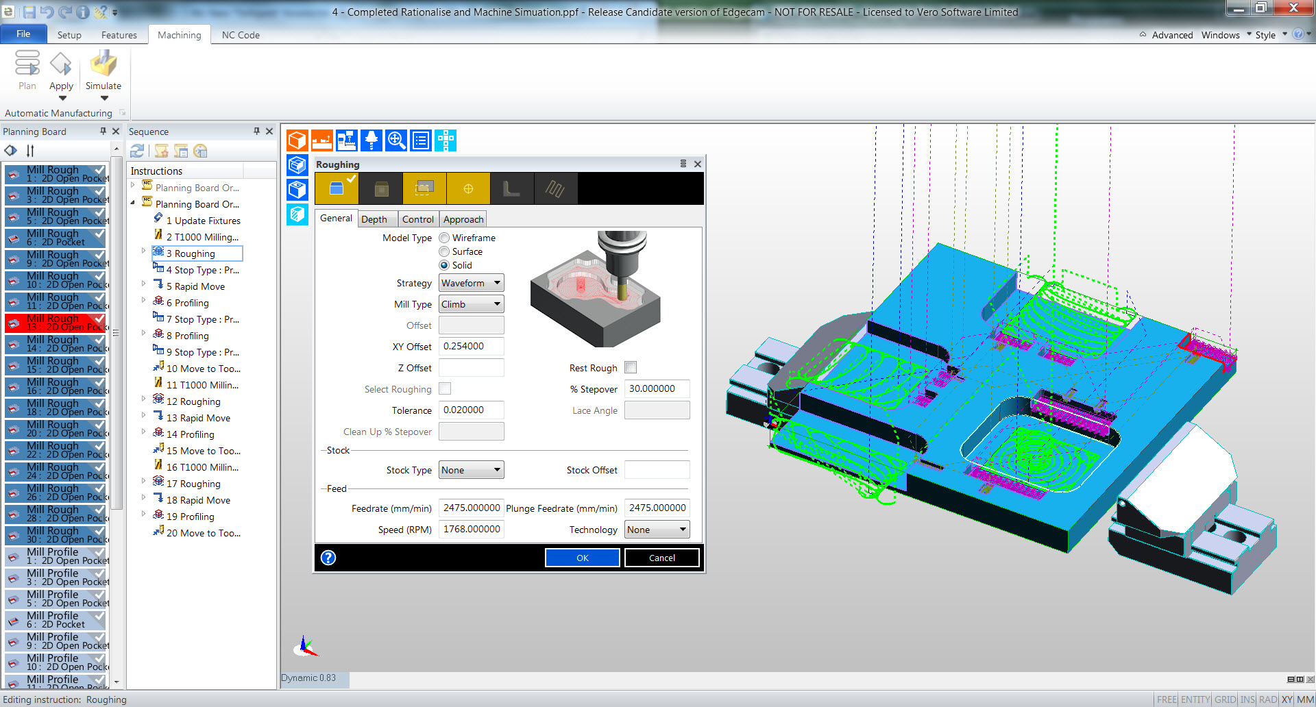
Dialogs
Part Modeler
Simulator
Simulator now runs as a separate process to EDGECAM providing the following benefits.
-
Simulator starts instantly on second start up; a major benefit when simulating large parts/div>
-
Simulator starts from where the simulation last finished; no need to run simulation from the start each time
-
pdate Stock is up to 50% quicker than the previous release.
Simulator rendering has been enhanced. By default, stock surfaces are rendered with a metallic look. And a Flat Rendering option has been added to render the surfaces with a non-metallic look. Rapid Result has been improved for this release and Tool graphics are now displayed, with Toggle Tool and Toggle Tool Holders buttons enabled.
Wire Profile
A new Wire Profile Feature command has been added to find features suitable for Wire Erosion from a solid. This facility removes the need to extract the edges from the solid to make the wireframe fences. Other improvements to the Wire EDM include:
- Faces can be picked individually, by window or chained
- Selected faces can have differing levels and heights; they do not need to be on parallel planes
- It is possible to control the XY and UV Profile Height of the feature using controls on the feature dialog
- The identified Wire Features appear in the feature list and have their own list of properties.
Milling Enhancements
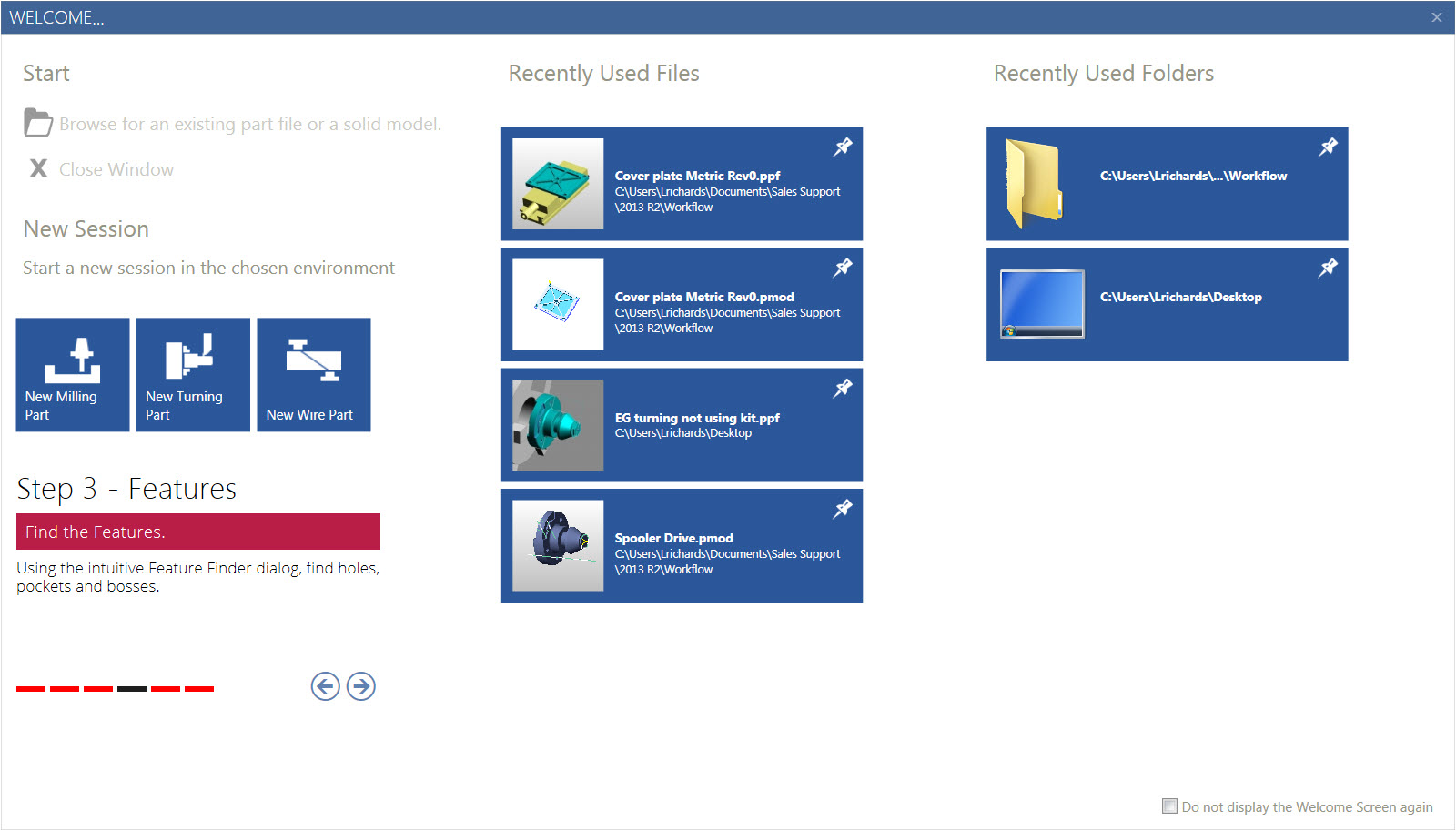
Rationalise - Merge Identical Roughing and Profiling cycles
Typically, when milling cycles are applied to features, they are applied feature by feature using the Planning Board. This can lead to multiple identical cycles in the sequence browser with, for example, one cycle for each pocket.
Rationalise can now merge these cycles into one cycle, as is already done for hole cycles. When merge milling cycles is checked in the Rationalise dialog, cycles that are machined by the same Tool on the same CPL and whose dialog settings are identical are merged.
The benefit of merging the cycles not only makes the machining sequence shorter and easier to manage but the merged cycles inherit the toolpath ordering of the cycle. Initially, this has been implemented for the Roughing and Profiling cycles.
Mill Cycles - Select Boundary Edges Direct from Solid
The Milling cycles have been updated to allow boundaries to be selected directly from Solid Edges of EdgeLoops without the need to create geometry edges or EdgeLoops first. If the edges are not parallel to the current CPL, they are automatically projected in to the CPL to form a 2D boundary.
Turning Enhancements
New Finish Groove Cycle
A new Finish Groove cycle utilising the same processing as the Finish Turn cycle has been implemented to provide capabilities not available previously and to improve compatibility between the cycles.
The main advantages are:
- Ability to change setting point depending on the side of tool in contact on the plunge moves
- Ability to output CRC control codes and to change that code when changing tool sides
- Ability to set an overlap
- Ability to control lead in and out
- Ability to split the cycle in the middle or side.
Finish Turning - Break First Entity enhanced
A new Break Orientation Angle setting has been added to the Control options allowing users to specify the angle of the theoretical element for which to break the first profile element. The angle of the theoretical element is controlled by an absolute user-supplied angle. If no angle is supplied then a right angle is assumed.
Strategy Manager Enhancements
User-defined Feature attributes for Strategies
Custom attributes can now be added to the Feature group of the attribute template which create new properties for Mill, Turn or Hole features. These attributes appear in the EDGECAM feature properties window and can be set to communicate information to a strategy to affect the manufacturing process.
Solid Machinist Enhancements
Merge Nested Groove Features
A new Merge Nested Groove Features Turn option is available on the Feature Finder dialog. The new option allows grooves to be merged into larger grooves.
Toolstore Enhancements
Support for Keyed Index Turrets
A Turret Holder Mating option has been added to the Tool Mounting Parameters providing for machines fitted with index turrets that have keyed recesses into which pre-assembled keyed tool holders can be mounted.
Holder Origin Options
New Holder Origin possibilities make it easy to position the Tool Holder graphic.
A Holder Origin option has been added to the Tool Mounting Parameters which can be set to either the Insert Centre (Turning tools) or Flute Height (Milling and Hole tools), Tool Tip or Gauge Datum
Coolant Options
A Coolant option has been added to the Tool Mounting Parameters allowing you to specify whether the tool can pass coolant and the method used (Off, Flood, Mist or Air). The Through Coolant option in the Tool Geometry Parameters has been enhanced to provide a High Pressure selection.
Draw Tool Clearance
A Draw tool clearance option has been added to the Setting Preferences.
This option is used to display a ghosted image of the insert shape which will be used to generate the turn cycle offset including tool clearance angles.
Tooling Enhancements
Support for Keyed Index Turrets
Holder Origin Options
Code Wizard Enhancements
Inch / Metric conversion of CGDs